The 2LBB Programming Language
The programming language that is used here is 2L designed by Gregor Richards with some minor modifications proposed by Mathijs Romans to make it more suitable for the Busy Beaver problem. The resulting language is called 2LBB here.
Language
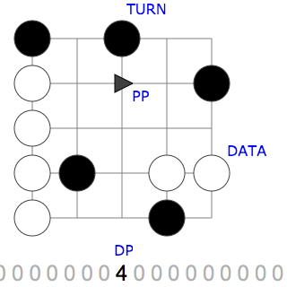
The language is two-dimensional. The instructions are put on a 2D grid with limited size. The directional program pointer (PP) moves across this grid, executing instructions as it encounters them. It starts just below the left-most cell at the bottom of the grid, moving upwards.
There is also a one-dimensional, infinite tape that acts as data. All cells of the tape are initially filled with zeros. The data pointer (DP) points to one of these cells.
The language consist of only two symbols:
-
TURN, visualised by a Black symbol
When PP would enter a cell with a TURN instruction, it changes direction to prevent this. The direction it turns to depends on the value that DP points to:- When the value is zero, PP turns ninety degrees counter-clockwise
- Otherwise, PP turns ninety degrees clockwise
-
DATA, visualised by a White symbol
What happens when PP enters a cell with a DATA instruction depends on the direction of PP:- When it is moving up, it increases the value at DP by one
- When it is moving down, it decreases the value at DP by one
- When it is moving right, it moves DP one position to the right
- When it is moving left, it moves DP one position to the left
Program cells can also be empty, representing a NOOP instruction; PP simply keeps moving in its current direction.
The program terminates when PP leaves the board.
Figure 1 shows a visualisation of 2LBB, annotated with the above terms.
Modifications
Compared to the original 2L language, 2LBB differs as follows:
- the data tape does not have cells for I/O operations,
- the data tape is infinite in both directions,
- the program space is bounded, and
- the mapping of PP direction to the actual operation is changed for the DATA symbol (to be more intuitive)
An example program
A program that uses all operations is shown in Figure 2 below. Use the button to step through the program. At the bottom right you will see a step counter appear. The program does the following:
- Step 2-3: The first two DATA instructions each increase the value at DP by one so that it becomes two
- Step 4: As a result, the first TURN is clockwise
- Step 7-8: The next two DATA instructions each shift DP one position to the right
- Step 9: The data at DP is now zero, so the second TURN is counter clockwise
- Step 11: The third TURN is counter clockwise for the same reason
- Step 12: The fifth DATA instruction moves DP one position to the left
- Step 13: The data at DP is still zero, so the fourth TURN is also counter clockwise
- Step 15: The sixth DATA instruction has already been visited, but from a different direction. This time, it decreases the value at DP by one to -1
- Step 17: As the active data value is non-zero the fifth TURN is clockwise
- Step 20: PP encounters another instruction that it visited before, but again from a different direction. Now it results in moving DP a step to the left
- Step 21: PP leaves the program grid thereby terminating the program
Figure 3 shows a program that is equivalent to the one in Figure 2, but condensed to fit on a smaller grid.